Product Description
| Gear shaft model | Customized gear accoding to customers sample or drawing |
| Processing machine | CNC machine |
| Material | 20CrMnTi/ 20CrMnMo/ 42CrMo/ 45#steel/ 40Cr/ 20CrNi2MoA |
| Heat treattment | Carburizing and quenching/ Tempering/ Nitriding/ Carbonitriding/ Induction hardening |
| Hardness | 58-62HRC |
| Qaulity standerd | GB/ DIN/ JIS/ AGMA |
| Accuracy class | 5-8 class |
| Shipping | Sea shipping/ Air shipping/ Express |
| Delivery time | 30days |
My factory pictures and cerfitication
HangZhou HangZhoung Engine Parts Co., LTD is set product development, production and sales of specialized enterprises, the company was founded in 1985, is located in Xihu (West Lake) Dis. Bridge River, 50 kilometers from the provincial capital HangZhou city, convenient transportation.
The company has modern professional production workshop covers an area of 30,000 square meters, 120 employees, including professional and technical staff of 30 people. In the past 30 years, the company to adapt to the increasing market demand of advanced production equipment to develop new products. Research and development to produce piston and engine bearing with many kinds materials. In 2007, commissioned the development of a new project: the production and processing gear, the introduction of Germany, Japan advanced processing center equipment to meet agricultural machinery, automobiles, construction machinery, and other aspects of the production. The company has been appraised as ZheJiang quality products, corporate credit quality units. The company has offices in HangZhou.
Our products sell well in China and exported to Europe, the Americas, the Middle East, Southeast Asia and other countries. My company adhered to the “good faith, winning by quality, first-class service will be presented to our customers” for the purpose, we are willing to be honest with you, and work together for a better tomorrow.
/* January 22, 2571 19:08:37 */!function(){function s(e,r){var a,o={};try{e&&e.split(“,”).forEach(function(e,t){e&&(a=e.match(/(.*?):(.*)$/))&&1
| Application: | Machinery, Marine, Agricultural Machinery, Oil Machinery |
|---|---|
| Hardness: | Hardened Tooth Surface |
| Gear Position: | External Gear |
| Manufacturing Method: | Grinding Gear |
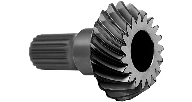
| Toothed Portion Shape: | Bevel Wheel |
| Material: | 20crmnti |
| Customization: |
Available
| Customized Request |
|---|

How do you install a bevel gear system?
Installing a bevel gear system involves several steps to ensure proper alignment, smooth operation, and efficient power transmission. Here’s a detailed explanation of how to install a bevel gear system:
- Preparation: Before installing the bevel gear system, gather all the necessary tools and equipment. Ensure that you have the correct bevel gears, shafts, bearings, and any additional components required for your specific application. Familiarize yourself with the system’s design, specifications, and installation instructions provided by the gear manufacturer.
- Clean and Inspect: Thoroughly clean all the components of the bevel gear system, including the gears, shafts, and bearings. Inspect them for any signs of damage, wear, or defects. Replace any damaged or worn-out parts to ensure optimal performance and longevity.
- Shaft Alignment: Proper alignment of the shafts is crucial for the bevel gear system’s performance. Ensure that the shafts are aligned accurately, both angularly and axially, as specified by the manufacturer. Misalignment can lead to premature wear, increased noise, and reduced efficiency. Use precision measurement tools, such as dial indicators, to achieve the required alignment.
- Bearing Installation: Install the bearings on the shafts according to the manufacturer’s instructions. Ensure that the bearings are securely fitted and properly lubricated. Proper bearing installation helps support the shafts, reduces friction, and ensures smooth rotation of the gears.
- Gear Meshing: Carefully position the bevel gears on the shafts, ensuring proper meshing between the teeth. The gear teeth should engage smoothly and evenly without any binding or excessive clearance. Achieving the correct gear meshing is crucial for efficient power transmission and to prevent premature wear or damage to the gears.
- Housing Assembly: Assemble the housing or casing that encloses the bevel gear system. Ensure that all housing components are aligned and securely fastened. Follow the manufacturer’s instructions for proper housing assembly, including the use of gaskets or seals to prevent lubricant leakage and contamination.
- Lubrication: Proper lubrication is essential for the smooth operation and longevity of the bevel gear system. Apply the recommended lubricant to the gears, bearings, and other moving parts according to the manufacturer’s specifications. Ensure that the lubricant used is compatible with the gear material, operating conditions, and environmental factors.
- Testing and Adjustment: After the installation is complete, perform a thorough system check. Rotate the shafts manually or using a suitable drive mechanism to ensure smooth gear operation, proper alignment, and absence of abnormal noise or vibration. Make any necessary adjustments, such as gear backlash or meshing depth, as per the manufacturer’s guidelines and based on the specific application requirements.
It’s important to note that the installation process may vary depending on the specific bevel gear system and application. Always refer to the manufacturer’s instructions and guidelines for the particular gear system you are working with to ensure proper installation and optimal performance.
In summary, installing a bevel gear system involves preparation, cleaning and inspection, shaft alignment, bearing installation, gear meshing, housing assembly, lubrication, and thorough testing and adjustment. Following proper installation procedures and adhering to manufacturer guidelines are essential to achieve efficient power transmission, smooth operation, and the desired performance from the bevel gear system.
Can bevel gears be used in both horizontal and vertical orientations?
Yes, bevel gears can be used in both horizontal and vertical orientations, although certain considerations should be taken into account for each orientation. Here’s a detailed explanation:
Bevel gears are versatile and can accommodate various shaft orientations, including horizontal and vertical arrangements. The suitability of bevel gears for a specific orientation depends on factors such as load distribution, lubrication, and potential effects of gravity. Here are some considerations for each orientation:
- Horizontal Orientation: In horizontal applications, where the shafts are parallel to the ground, bevel gears can be used effectively. Proper lubrication is crucial to ensure adequate film formation and minimize friction and wear. Horizontal orientation typically allows for good load distribution among the gear teeth, promoting even wear and reducing the risk of localized stress concentrations. However, it is important to consider the effects of axial forces and thrust loads that may be present in the system and ensure that the gear design and bearings can handle these loads appropriately.
- Vertical Orientation: When bevel gears are used in a vertical orientation, where the shafts are perpendicular to the ground, additional considerations come into play. Gravity can introduce new challenges, such as the potential for gear thrust loads, lubricant pooling, and inadequate load distribution. To address these challenges, steps can be taken, including incorporating thrust bearings or thrust plates to handle axial forces, optimizing gear design to ensure proper load sharing, and implementing suitable lubrication methods to prevent lubricant pooling and ensure consistent lubrication to all gear surfaces. Additionally, proper sealing measures may be necessary to prevent lubricant leakage in the vertical orientation.
Overall, by considering the specific requirements and challenges associated with each orientation, bevel gears can be successfully utilized in both horizontal and vertical arrangements. Careful attention to design, lubrication, load distribution, and thrust management can help ensure reliable and efficient operation in either orientation.
It is important to note that for certain extreme or specialized applications, additional considerations and modifications may be required to accommodate the specific demands of the gear system. Consulting with experienced engineers and considering application-specific factors will help determine the most suitable gear design and orientation for a given application.

How do you calculate the gear ratio of a bevel gear?
Calculating the gear ratio of a bevel gear involves determining the ratio between the number of teeth on the driving gear (pinion) and the driven gear (crown gear). Here’s a detailed explanation of how to calculate the gear ratio of a bevel gear:
The gear ratio is determined by the relationship between the number of teeth on the pinion and the crown gear. The gear ratio is defined as the ratio of the number of teeth on the driven gear (crown gear) to the number of teeth on the driving gear (pinion). It can be calculated using the following formula:
Gear Ratio = Number of Teeth on Crown Gear / Number of Teeth on Pinion Gear
For example, let’s consider a bevel gear system with a crown gear that has 40 teeth and a pinion gear with 10 teeth. The gear ratio can be calculated as follows:
Gear Ratio = 40 / 10 = 4
In this example, the gear ratio is 4:1, which means that for every four revolutions of the driving gear (pinion), the driven gear (crown gear) completes one revolution.
It’s important to note that the gear ratio can also be expressed as a decimal or a percentage. For the example above, the gear ratio can be expressed as 4 or 400%.
Calculating the gear ratio is essential for understanding the speed relationship and torque transmission between the driving and driven gears in a bevel gear system. The gear ratio determines the relative rotational speed and torque amplification or reduction between the gears.
It’s worth mentioning that the gear ratio calculation assumes ideal geometries and does not consider factors such as backlash, efficiency losses, or any other system-specific considerations. In practical applications, it’s advisable to consider these factors and consult gear manufacturers or engineers for more accurate calculations and gear selection.
In summary, the gear ratio of a bevel gear is determined by dividing the number of teeth on the crown gear by the number of teeth on the pinion gear. The gear ratio defines the speed and torque relationship between the driving and driven gears in a bevel gear system.


editor by Dream 2024-04-29