Product Description
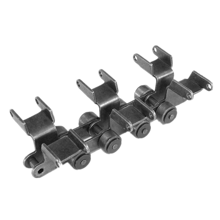
SPROCKET 1/2” X 5/16” 08B SERIES SPROCKETS
| For Chain Acc.to DIN8187 ISO/R 606 | |||||
| Tooth Radius r3 | 13.0mm | ||||
| Radius Width C | 1.3mm | ||||
| Tooth Width b1 | 7.0mm | ||||
| Tooth Width B1 | 7.2mm | ||||
| Tooth Width B2 | 21.0mm | ||||
| Tooth Width B3 | 34.9mm | ||||
| 08B SERIES ROLLER CHAINS | |||||
| Pitch | 12.7 mm | ||||
| Internal Width | 7.75 mm | ||||
| Roller Diameter | 8.51 mm | ||||
| Z | de | dp | SIMPLEX | DUPLEX | TRIPLEX |
| D1 | D2 | D3 | |||
| 8 | 37.2 | 33.18 | 8 | 10 | 10 |
| 9 | 41.0 | 37.13 | 8 | 10 | 10 |
| 10 | 45.2 | 41.10 | 8 | 10 | 10 |
| 11 | 48.7 | 45.07 | 10 | 10 | 12 |
| 12 | 53.0 | 49.07 | 10 | 10 | 12 |
| 13 | 57.4 | 53.06 | 10 | 10 | 12 |
| 14 | 61.8 | 57.07 | 10 | 10 | 12 |
| 15 | 65.5 | 61.09 | 10 | 10 | 12 |
| 16 | 69.5 | 65.10 | 10 | 12 | 16 |
| 17 | 73.6 | 69.11 | 10 | 12 | 16 |
| 18 | 77.8 | 73.14 | 10 | 12 | 16 |
| 19 | 81.7 | 77.16 | 10 | 12 | 16 |
| 20 | 85.8 | 81.19 | 10 | 12 | 16 |
| 21 | 89.7 | 85.22 | 12 | 16 | 16 |
| 22 | 93.8 | 89.24 | 12 | 16 | 16 |
| 23 | 98.2 | 93.27 | 12 | 16 | 16 |
| 24 | 101.8 | 97.29 | 12 | 16 | 16 |
| 25 | 105.8 | 101.33 | 12 | 16 | 16 |
| 26 | 110.0 | 105.36 | 16 | 16 | 16 |
| 27 | 114.0 | 109.40 | 16 | 16 | 16 |
| 28 | 118.0 | 113.42 | 16 | 16 | 16 |
| 29 | 122.0 | 117.46 | 16 | 16 | 16 |
| 30 | 126.1 | 121.50 | 16 | 16 | 16 |
| 31 | 130.2 | 125.54 | 16 | 16 | 20 |
| 32 | 134.3 | 129.56 | 16 | 16 | 20 |
| 33 | 138.4 | 133.60 | 16 | 16 | 20 |
| 34 | 142.6 | 137.64 | 16 | 16 | 20 |
| 35 | 146.7 | 141.68 | 16 | 16 | 20 |
| 36 | 151.0 | 145.72 | 16 | 20 | 20 |
| 37 | 154.6 | 149.76 | 16 | 20 | 20 |
| 38 | 158.6 | 153.80 | 16 | 20 | 20 |
| 39 | 162.7 | 157.83 | 16 | 20 | 20 |
| 40 | 166.8 | 161.87 | 16 | 20 | 20 |
| 41 | 171.4 | 165.91 | 20 | 20 | 25 |
| 42 | 175.4 | 169.94 | 20 | 20 | 25 |
| 43 | 179.7 | 173.98 | 20 | 20 | 25 |
| 44 | 183.8 | 178.02 | 20 | 20 | 25 |
| 45 | 188.0 | 182.07 | 20 | 20 | 25 |
| 46 | 192.1 | 186.10 | 20 | 20 | 25 |
| 47 | 196.2 | 190.14 | 20 | 20 | 25 |
| 48 | 200.3 | 194.18 | 20 | 20 | 25 |
| 49 | 204.3 | 198.22 | 20 | 20 | 25 |
| 50 | 208.3 | 202.26 | 20 | 20 | 25 |
| 51 | 212.1 | 206.30 | 20 | 25 | 25 |
| 52 | 216.1 | 210.34 | 20 | 25 | 25 |
| 53 | 220.2 | 214.37 | 20 | 25 | 25 |
| 54 | 224.1 | 218.43 | 20 | 25 | 25 |
| 55 | 228.1 | 222.46 | 20 | 25 | 25 |
| 56 | 232.2 | 226.50 | 20 | 25 | 25 |
| 57 | 236.4 | 230.54 | 20 | 25 | 25 |
| 58 | 240.5 | 234.58 | 20 | 25 | 25 |
| 59 | 244.5 | 238.62 | 20 | 25 | 25 |
| 60 | 248.6 | 242.66 | 20 | 25 | 25 |
| 62 | 256.9 | 250.74 | 25 | 25 | 25 |
| 64 | 265.1 | 258.82 | 25 | 25 | 25 |
| 65 | 269.0 | 262.86 | 25 | 25 | 25 |
| 66 | 273.0 | 266.91 | 25 | 25 | 25 |
| 68 | 281.0 | 274.99 | 25 | 25 | 25 |
| 70 | 289.0 | 283.07 | 25 | 25 | 25 |
| 72 | 297.2 | 291.15 | 25 | 25 | 25 |
| 75 | 309.2 | 303.28 | 25 | 25 | 25 |
| 76 | 313.2 | 307.32 | 25 | 25 | 25 |
| 78 | 321.4 | 315.40 | 25 | 25 | 25 |
| 80 | 329.4 | 323.49 | 25 | 25 | 25 |
| 85 | 349.0 | 343.69 | 25 | 25 | 25 |
| 90 | 369.9 | 363.90 | 25 | 25 | 25 |
| 95 | 390.1 | 384.11 | 25 | 25 | 25 |
| 100 | 410.3 | 404.32 | 25 | 25 | 25 |
| 110 | 450.7 | 444.74 | 25 | 25 | 25 |
| 114 | 466.9 | 460.91 | 25 | 25 | 25 |
| 120 | 491.2 | 485.16 | 25 | 25 | 25 |
| 125 | 511.3 | 505.37 | 25 | 25 | 25 |
BASIC INFO.
|
Type: |
Simplex, Duplex, Triplex |
|
Sprocket Model: |
3/8″,1/2″,5/8″,3/4″,1″,1.25″,1.50″,1.75″,2.00″,2.25″,2.00″,2.25″,2.50″, 3″ |
|
Teeth Number: |
9-100 |
|
Standard: |
ANSI , JIS, DIN, ISO |
|
Material: |
1571, 1045, SS304 , SS316; As Per User Request. |
|
Performance Treatment: |
Carburizing, High Frequency Treatment, Hardening and Tempering, Nitriding |
|
Surface Treatment: |
Black of Oxidation, Zincing, Nickelage. |
| Characteristic | Fire Resistant, Oil Resistant, Heat Resistant, CZPT resistance, Oxidative resistance, Corrosion resistance, etc |
| Design criterion | ISO DIN ANSI & Customer Drawings |
| Application | Industrial transmission equipment |
| Package | Wooden Case / Container and pallet, or made-to-order |
|
Certification: |
ISO9001 SGS |
|
Quality Inspection: |
Self-check and Final-check |
|
Sample: |
ODM&OEM, Trial Order Available and Welcome |
| Advantage | Quality first, Service first, Competitive price, Fast delivery |
| Delivery Time | 10 days for samples. 15 days for official order. |
INSTALLATION AND USING
The chain spocket, as a drive or deflection for chains, has pockets to hold the chain links with a D-profile cross section with flat side surfaces parallel to the centre plane of the chain links, and outer surfaces at right angles to the chain link centre plane. The chain links are pressed firmly against the outer surfaces and each of the side surfaces by the angled laying surfaces at the base of the pockets, and also the support surfaces of the wheel body together with the end sides of the webs formed by the leading and trailing walls of the pocket.
NOTICE
When fitting new chainwheels it is very important that a new chain is fitted at the same time, and vice versa. Using an old chain with new sprockets, or a new chain with old sprockets will cause rapid wear.
It is important if you are installing the chainwheels yourself to have the factory service manual specific to your model. Our chainwheels are made to be a direct replacement for your OEM chainwheels and as such, the installation should be performed according to your models service manual.
During use a chain will stretch (i.e. the pins will wear causing extension of the chain). Using a chain which has been stretched more than the above maximum allowance causes the chain to ride up the teeth of the sprocket. This causes damage to the tips of the chainwheels teeth, as the force transmitted by the chain is transmitted entirely through the top of the tooth, rather than the whole tooth. This results in severe wearing of the chainwheel.
FOR CHAIN STHangZhouRDS
Standards organizations (such as ANSI and ISO) maintain standards for design, dimensions, and interchangeability of transmission chains. For example, the following Table shows data from ANSI standard B29.1-2011 (Precision Power Transmission Roller Chains, Attachments, and Sprockets) developed by the American Society of Mechanical Engineers (ASME). See the references[8][9][10] for additional information.
ASME/ANSI B29.1-2011 Roller Chain Standard SizesSizePitchMaximum Roller DiameterMinimum Ultimate Tensile StrengthMeasuring Load25
| ASME/ANSI B29.1-2011 Roller Chain Standard Sizes | ||||
| Size | Pitch | Maximum Roller Diameter | Minimum Ultimate Tensile Strength | Measuring Load |
|---|---|---|---|---|
| 25 | 0.250 in (6.35 mm) | 0.130 in (3.30 mm) | 780 lb (350 kg) | 18 lb (8.2 kg) |
| 35 | 0.375 in (9.53 mm) | 0.200 in (5.08 mm) | 1,760 lb (800 kg) | 18 lb (8.2 kg) |
| 41 | 0.500 in (12.70 mm) | 0.306 in (7.77 mm) | 1,500 lb (680 kg) | 18 lb (8.2 kg) |
| 40 | 0.500 in (12.70 mm) | 0.312 in (7.92 mm) | 3,125 lb (1,417 kg) | 31 lb (14 kg) |
| 50 | 0.625 in (15.88 mm) | 0.400 in (10.16 mm) | 4,880 lb (2,210 kg) | 49 lb (22 kg) |
| 60 | 0.750 in (19.05 mm) | 0.469 in (11.91 mm) | 7,030 lb (3,190 kg) | 70 lb (32 kg) |
| 80 | 1.000 in (25.40 mm) | 0.625 in (15.88 mm) | 12,500 lb (5,700 kg) | 125 lb (57 kg) |
| 100 | 1.250 in (31.75 mm) | 0.750 in (19.05 mm) | 19,531 lb (8,859 kg) | 195 lb (88 kg) |
| 120 | 1.500 in (38.10 mm) | 0.875 in (22.23 mm) | 28,125 lb (12,757 kg) | 281 lb (127 kg) |
| 140 | 1.750 in (44.45 mm) | 1.000 in (25.40 mm) | 38,280 lb (17,360 kg) | 383 lb (174 kg) |
| 160 | 2.000 in (50.80 mm) | 1.125 in (28.58 mm) | 50,000 lb (23,000 kg) | 500 lb (230 kg) |
| 180 | 2.250 in (57.15 mm) | 1.460 in (37.08 mm) | 63,280 lb (28,700 kg) | 633 lb (287 kg) |
| 200 | 2.500 in (63.50 mm) | 1.562 in (39.67 mm) | 78,175 lb (35,460 kg) | 781 lb (354 kg) |
| 240 | 3.000 in (76.20 mm) | 1.875 in (47.63 mm) | 112,500 lb (51,000 kg) | 1,000 lb (450 kg |
For mnemonic purposes, below is another presentation of key dimensions from the same standard, expressed in fractions of an inch (which was part of the thinking behind the choice of preferred numbers in the ANSI standard):
| Pitch (inches) | Pitch expressed in eighths |
ANSI standard chain number |
Width (inches) |
|---|---|---|---|
| 1⁄4 | 2⁄8 | 25 | 1⁄8 |
| 3⁄8 | 3⁄8 | 35 | 3⁄16 |
| 1⁄2 | 4⁄8 | 41 | 1⁄4 |
| 1⁄2 | 4⁄8 | 40 | 5⁄16 |
| 5⁄8 | 5⁄8 | 50 | 3⁄8 |
| 3⁄4 | 6⁄8 | 60 | 1⁄2 |
| 1 | 8⁄8 | 80 | 5⁄8 |
Notes:
1. The pitch is the distance between roller centers. The width is the distance between the link plates (i.e. slightly more than the roller width to allow for clearance).
2. The right-hand digit of the standard denotes 0 = normal chain, 1 = lightweight chain, 5 = rollerless bushing chain.
3. The left-hand digit denotes the number of eighths of an inch that make up the pitch.
4. An “H” following the standard number denotes heavyweight chain. A hyphenated number following the standard number denotes double-strand (2), triple-strand (3), and so on. Thus 60H-3 denotes number 60 heavyweight triple-strand chain.
A typical bicycle chain (for derailleur gears) uses narrow 1⁄2-inch-pitch chain. The width of the chain is variable, and does not affect the load capacity. The more sprockets at the rear wheel (historically 3-6, nowadays 7-12 sprockets), the narrower the chain. Chains are sold according to the number of speeds they are designed to work with, for example, “10 speed chain”. Hub gear or single speed bicycles use 1/2″ x 1/8″ chains, where 1/8″ refers to the maximum thickness of a sprocket that can be used with the chain.
Typically chains with parallel shaped links have an even number of links, with each narrow link followed by a broad one. Chains built up with a uniform type of link, narrow at 1 and broad at the other end, can be made with an odd number of links, which can be an advantage to adapt to a special chainwheel-distance; on the other side such a chain tends to be not so strong.
Roller chains made using ISO standard are sometimes called as isochains.
WHY CHOOSE US
1. Reliable Quality Assurance System
2. Cutting-Edge Computer-Controlled CNC Machines
3. Bespoke Solutions from Highly Experienced Specialists
4. Customization and OEM Available for Specific Application
5. Extensive Inventory of Spare Parts and Accessories
6. Well-Developed CZPT Marketing Network
7. Efficient After-Sale Service System
The 219 sets of advanced automatic production equipment provide guarantees for high product quality. The 167 engineers and technicians with senior professional titles can design and develop products to meet the exact demands of customers, and OEM customizations are also available with us. Our sound global service network can provide customers with timely after-sales technical services.
We are not just a manufacturer and supplier, but also an industry consultant. We work pro-actively with you to offer expert advice and product recommendations in order to end up with a most cost effective product available for your specific application. The clients we serve CZPT range from end users to distributors and OEMs. Our OEM replacements can be substituted wherever necessary and suitable for both repair and new assemblies.
| Standard Or Nonstandard: | Standard |
|---|---|
| Application: | Motor, Electric Cars, Motorcycle, Machinery, Marine, Toy, Agricultural Machinery, Car, Mining Machinery, Sugar Machinery |
| Hardness: | Hardened Tooth Surface |
| Manufacturing Method: | Cut Gear |
| Toothed Portion Shape: | Spur Gear |
| Material: | Alloy |
| Samples: |
US$ 0/Piece
1 Piece(Min.Order) | |
|---|
| Customization: |
Available
| Customized Request |
|---|

The Difference Between Planetary Gears and Spur Gears
A spur gear is a type of mechanical drive that turns an external shaft. The angular velocity is proportional to the rpm and can be easily calculated from the gear ratio. However, to properly calculate angular velocity, it is necessary to know the number of teeth. Fortunately, there are several different types of spur gears. Here’s an overview of their main features. This article also discusses planetary gears, which are smaller, more robust, and more power-dense.
Planetary gears are a type of spur gear
One of the most significant differences between planetary gears and spurgears is the way that the two share the load. Planetary gears are much more efficient than spurgears, enabling high torque transfer in a small space. This is because planetary gears have multiple teeth instead of just one. They are also suitable for intermittent and constant operation. This article will cover some of the main benefits of planetary gears and their differences from spurgears.
While spur gears are more simple than planetary gears, they do have some key differences. In addition to being more basic, they do not require any special cuts or angles. Moreover, the tooth shape of spur gears is much more complex than those of planetary gears. The design determines where the teeth make contact and how much power is available. However, a planetary gear system will be more efficient if the teeth are lubricated internally.
In a planetary gear, there are three shafts: a sun gear, a planet carrier, and an external ring gear. A planetary gear is designed to allow the motion of one shaft to be arrested, while the other two work simultaneously. In addition to two-shaft operation, planetary gears can also be used in three-shaft operations, which are called temporary three-shaft operations. Temporary three-shaft operations are possible through frictional coupling.
Among the many benefits of planetary gears is their adaptability. As the load is shared between several planet gears, it is easier to switch gear ratios, so you do not need to purchase a new gearbox for every new application. Another major benefit of planetary gears is that they are highly resistant to high shock loads and demanding conditions. This means that they are used in many industries.
They are more robust
An epicyclic gear train is a type of transmission that uses concentric axes for input and output. This type of transmission is often used in vehicles with automatic transmissions, such as a Lamborghini Gallardo. It is also used in hybrid cars. These types of transmissions are also more robust than conventional planetary gears. However, they require more assembly time than a conventional parallel shaft gear.
An epicyclic gearing system has three basic components: an input, an output, and a carrier. The number of teeth in each gear determines the ratio of input rotation to output rotation. In some cases, an epicyclic gear system can be made with two planets. A third planet, known as the carrier, meshes with the second planet and the sun gear to provide reversibility. A ring gear is made of several components, and a planetary gear may contain many gears.
An epicyclic gear train can be built so that the planet gear rolls inside the pitch circle of an outer fixed gear ring, or “annular gear.” In such a case, the curve of the planet’s pitch circle is called a hypocycloid. When epicycle gear trains are used in combination with a sun gear, the planetary gear train is made up of both types. The sun gear is usually fixed, while the ring gear is driven.
Planetary gearing, also known as epicyclic gear, is more durable than other types of transmissions. Because planets are evenly distributed around the sun, they have an even distribution of gears. Because they are more robust, they can handle higher torques, reductions, and overhung loads. They are also more energy-dense and robust. In addition, planetary gearing is often able to be converted to various ratios.
They are more power dense
The planet gear and ring gear of a compound planetary transmission are epicyclic stages. One part of the planet gear meshes with the sun gear, while the other part of the gear drives the ring gear. Coast tooth flanks are used only when the gear drive works in reversed load direction. Asymmetry factor optimization equalizes the contact stress safety factors of a planetary gear. The permissible contact stress, sHPd, and the maximum operating contact stress (sHPc) are equalized by asymmetry factor optimization.
In addition, epicyclic gears are generally smaller and require fewer space than helical ones. They are commonly used as differential gears in speed frames and in looms, where they act as a Roper positive let off. They differ in the amount of overdrive and undergearing ratio they possess. The overdrive ratio varies from fifteen percent to forty percent. In contrast, the undergearing ratio ranges from 0.87:1 to 69%.
The TV7-117S turboprop engine gearbox is the first known application of epicyclic gears with asymmetric teeth. This gearbox was developed by the CZPT Corporation for the Ilyushin Il-114 turboprop plane. The TV7-117S’s gearbox arrangement consists of a first planetary-differential stage with three planet gears and a second solar-type coaxial stage with five planet gears. This arrangement gives epicyclic gears the highest power density.
Planetary gearing is more robust and power-dense than other types of gearing. They can withstand higher torques, reductions, and overhung loads. Their unique self-aligning properties also make them highly versatile in rugged applications. It is also more compact and lightweight. In addition to this, epicyclic gears are easier to manufacture than planetary gears. And as a bonus, they are much less expensive.
They are smaller
Epicyclic gears are small mechanical devices that have a central “sun” gear and one or more outer intermediate gears. These gears are held in a carrier or ring gear and have multiple mesh considerations. The system can be sized and speeded by dividing the required ratio by the number of teeth per gear. This process is known as gearing and is used in many types of gearing systems.
Planetary gears are also known as epicyclic gearing. They have input and output shafts that are coaxially arranged. Each planet contains a gear wheel that meshes with the sun gear. These gears are small and easy to manufacture. Another advantage of epicyclic gears is their robust design. They are easily converted into different ratios. They are also highly efficient. In addition, planetary gear trains can be designed to operate in multiple directions.
Another advantage of epicyclic gearing is their reduced size. They are often used for small-scale applications. The lower cost is associated with the reduced manufacturing time. Epicyclic gears should not be made on N/C milling machines. The epicyclic carrier should be cast and tooled on a single-purpose machine, which has several cutters cutting through material. The epicyclic carrier is smaller than the epicyclic gear.
Epicyclic gearing systems consist of three basic components: an input, an output, and a stationary component. The number of teeth in each gear determines the ratio of input rotation to output rotation. Typically, these gear sets are made of three separate pieces: the input gear, the output gear, and the stationary component. Depending on the size of the input and output gear, the ratio between the two components is greater than half.
They have higher gear ratios
The differences between epicyclic gears and regular, non-epicyclic gears are significant for many different applications. In particular, epicyclic gears have higher gear ratios. The reason behind this is that epicyclic gears require multiple mesh considerations. The epicyclic gears are designed to calculate the number of load application cycles per unit time. The sun gear, for example, is +1300 RPM. The planet gear, on the other hand, is +1700 RPM. The ring gear is also +1400 RPM, as determined by the number of teeth in each gear.
Torque is the twisting force of a gear, and the bigger the gear, the higher the torque. However, since the torque is also proportional to the size of the gear, bigger radii result in lower torque. In addition, smaller radii do not move cars faster, so the higher gear ratios do not move at highway speeds. The tradeoff between speed and torque is the gear ratio.
Planetary gears use multiple mechanisms to increase the gear ratio. Those using epicyclic gears have multiple gear sets, including a sun, a ring, and two planets. Moreover, the planetary gears are based on helical, bevel, and spur gears. In general, the higher gear ratios of epicyclic gears are superior to those of planetary gears.
Another example of planetary gears is the compound planet. This gear design has two different-sized gears on either end of a common casting. The large end engages the sun while the smaller end engages the annulus. The compound planets are sometimes necessary to achieve smaller steps in gear ratio. As with any gear, the correct alignment of planet pins is essential for proper operation. If the planets are not aligned properly, it may result in rough running or premature breakdown.


editor by CX 2023-05-19
China wholesaler Gearbox Belt Conveyor Roller Chains Driving Chains Transmission Stainless Steel Chain and Sprocket Kit Oil Industry Gears Bevel Gear worm and wheel gear
Product Description
SPROCKET 1/2” X 5/16” 08B SERIES SPROCKETS
| For Chain Acc.to DIN8187 ISO/R 606 | |||||
| Tooth Radius r3 | 13.0mm | ||||
| Radius Width C | 1.3mm | ||||
| Tooth Width b1 | 7.0mm | ||||
| Tooth Width B1 | 7.2mm | ||||
| Tooth Width B2 | 21.0mm | ||||
| Tooth Width B3 | 34.9mm | ||||
| 08B SERIES ROLLER CHAINS | |||||
| Pitch | 12.7 mm | ||||
| Internal Width | 7.75 mm | ||||
| Roller Diameter | 8.51 mm | ||||
| Z | de | dp | SIMPLEX | DUPLEX | TRIPLEX |
| D1 | D2 | D3 | |||
| 8 | 37.2 | 33.18 | 8 | 10 | 10 |
| 9 | 41.0 | 37.13 | 8 | 10 | 10 |
| 10 | 45.2 | 41.10 | 8 | 10 | 10 |
| 11 | 48.7 | 45.07 | 10 | 10 | 12 |
| 12 | 53.0 | 49.07 | 10 | 10 | 12 |
| 13 | 57.4 | 53.06 | 10 | 10 | 12 |
| 14 | 61.8 | 57.07 | 10 | 10 | 12 |
| 15 | 65.5 | 61.09 | 10 | 10 | 12 |
| 16 | 69.5 | 65.10 | 10 | 12 | 16 |
| 17 | 73.6 | 69.11 | 10 | 12 | 16 |
| 18 | 77.8 | 73.14 | 10 | 12 | 16 |
| 19 | 81.7 | 77.16 | 10 | 12 | 16 |
| 20 | 85.8 | 81.19 | 10 | 12 | 16 |
| 21 | 89.7 | 85.22 | 12 | 16 | 16 |
| 22 | 93.8 | 89.24 | 12 | 16 | 16 |
| 23 | 98.2 | 93.27 | 12 | 16 | 16 |
| 24 | 101.8 | 97.29 | 12 | 16 | 16 |
| 25 | 105.8 | 101.33 | 12 | 16 | 16 |
| 26 | 110.0 | 105.36 | 16 | 16 | 16 |
| 27 | 114.0 | 109.40 | 16 | 16 | 16 |
| 28 | 118.0 | 113.42 | 16 | 16 | 16 |
| 29 | 122.0 | 117.46 | 16 | 16 | 16 |
| 30 | 126.1 | 121.50 | 16 | 16 | 16 |
| 31 | 130.2 | 125.54 | 16 | 16 | 20 |
| 32 | 134.3 | 129.56 | 16 | 16 | 20 |
| 33 | 138.4 | 133.60 | 16 | 16 | 20 |
| 34 | 142.6 | 137.64 | 16 | 16 | 20 |
| 35 | 146.7 | 141.68 | 16 | 16 | 20 |
| 36 | 151.0 | 145.72 | 16 | 20 | 20 |
| 37 | 154.6 | 149.76 | 16 | 20 | 20 |
| 38 | 158.6 | 153.80 | 16 | 20 | 20 |
| 39 | 162.7 | 157.83 | 16 | 20 | 20 |
| 40 | 166.8 | 161.87 | 16 | 20 | 20 |
| 41 | 171.4 | 165.91 | 20 | 20 | 25 |
| 42 | 175.4 | 169.94 | 20 | 20 | 25 |
| 43 | 179.7 | 173.98 | 20 | 20 | 25 |
| 44 | 183.8 | 178.02 | 20 | 20 | 25 |
| 45 | 188.0 | 182.07 | 20 | 20 | 25 |
| 46 | 192.1 | 186.10 | 20 | 20 | 25 |
| 47 | 196.2 | 190.14 | 20 | 20 | 25 |
| 48 | 200.3 | 194.18 | 20 | 20 | 25 |
| 49 | 204.3 | 198.22 | 20 | 20 | 25 |
| 50 | 208.3 | 202.26 | 20 | 20 | 25 |
| 51 | 212.1 | 206.30 | 20 | 25 | 25 |
| 52 | 216.1 | 210.34 | 20 | 25 | 25 |
| 53 | 220.2 | 214.37 | 20 | 25 | 25 |
| 54 | 224.1 | 218.43 | 20 | 25 | 25 |
| 55 | 228.1 | 222.46 | 20 | 25 | 25 |
| 56 | 232.2 | 226.50 | 20 | 25 | 25 |
| 57 | 236.4 | 230.54 | 20 | 25 | 25 |
| 58 | 240.5 | 234.58 | 20 | 25 | 25 |
| 59 | 244.5 | 238.62 | 20 | 25 | 25 |
| 60 | 248.6 | 242.66 | 20 | 25 | 25 |
| 62 | 256.9 | 250.74 | 25 | 25 | 25 |
| 64 | 265.1 | 258.82 | 25 | 25 | 25 |
| 65 | 269.0 | 262.86 | 25 | 25 | 25 |
| 66 | 273.0 | 266.91 | 25 | 25 | 25 |
| 68 | 281.0 | 274.99 | 25 | 25 | 25 |
| 70 | 289.0 | 283.07 | 25 | 25 | 25 |
| 72 | 297.2 | 291.15 | 25 | 25 | 25 |
| 75 | 309.2 | 303.28 | 25 | 25 | 25 |
| 76 | 313.2 | 307.32 | 25 | 25 | 25 |
| 78 | 321.4 | 315.40 | 25 | 25 | 25 |
| 80 | 329.4 | 323.49 | 25 | 25 | 25 |
| 85 | 349.0 | 343.69 | 25 | 25 | 25 |
| 90 | 369.9 | 363.90 | 25 | 25 | 25 |
| 95 | 390.1 | 384.11 | 25 | 25 | 25 |
| 100 | 410.3 | 404.32 | 25 | 25 | 25 |
| 110 | 450.7 | 444.74 | 25 | 25 | 25 |
| 114 | 466.9 | 460.91 | 25 | 25 | 25 |
| 120 | 491.2 | 485.16 | 25 | 25 | 25 |
| 125 | 511.3 | 505.37 | 25 | 25 | 25 |
BASIC INFO.
|
Type: |
Simplex, Duplex, Triplex |
|
Sprocket Model: |
3/8″,1/2″,5/8″,3/4″,1″,1.25″,1.50″,1.75″,2.00″,2.25″,2.00″,2.25″,2.50″, 3″ |
|
Teeth Number: |
9-100 |
|
Standard: |
ANSI , JIS, DIN, ISO |
|
Material: |
1571, 1045, SS304 , SS316; As Per User Request. |
|
Performance Treatment: |
Carburizing, High Frequency Treatment, Hardening and Tempering, Nitriding |
|
Surface Treatment: |
Black of Oxidation, Zincing, Nickelage. |
| Characteristic | Fire Resistant, Oil Resistant, Heat Resistant, CZPT resistance, Oxidative resistance, Corrosion resistance, etc |
| Design criterion | ISO DIN ANSI & Customer Drawings |
| Application | Industrial transmission equipment |
| Package | Wooden Case / Container and pallet, or made-to-order |
|
Certification: |
ISO9001 SGS |
|
Quality Inspection: |
Self-check and Final-check |
|
Sample: |
ODM&OEM, Trial Order Available and Welcome |
| Advantage | Quality first, Service first, Competitive price, Fast delivery |
| Delivery Time | 10 days for samples. 15 days for official order. |
INSTALLATION AND USING
The chain spocket, as a drive or deflection for chains, has pockets to hold the chain links with a D-profile cross section with flat side surfaces parallel to the centre plane of the chain links, and outer surfaces at right angles to the chain link centre plane. The chain links are pressed firmly against the outer surfaces and each of the side surfaces by the angled laying surfaces at the base of the pockets, and also the support surfaces of the wheel body together with the end sides of the webs formed by the leading and trailing walls of the pocket.
NOTICE
When fitting new chainwheels it is very important that a new chain is fitted at the same time, and vice versa. Using an old chain with new sprockets, or a new chain with old sprockets will cause rapid wear.
It is important if you are installing the chainwheels yourself to have the factory service manual specific to your model. Our chainwheels are made to be a direct replacement for your OEM chainwheels and as such, the installation should be performed according to your models service manual.
During use a chain will stretch (i.e. the pins will wear causing extension of the chain). Using a chain which has been stretched more than the above maximum allowance causes the chain to ride up the teeth of the sprocket. This causes damage to the tips of the chainwheels teeth, as the force transmitted by the chain is transmitted entirely through the top of the tooth, rather than the whole tooth. This results in severe wearing of the chainwheel.
FOR CHAIN STHangZhouRDS
Standards organizations (such as ANSI and ISO) maintain standards for design, dimensions, and interchangeability of transmission chains. For example, the following Table shows data from ANSI standard B29.1-2011 (Precision Power Transmission Roller Chains, Attachments, and Sprockets) developed by the American Society of Mechanical Engineers (ASME). See the references[8][9][10] for additional information.
ASME/ANSI B29.1-2011 Roller Chain Standard SizesSizePitchMaximum Roller DiameterMinimum Ultimate Tensile StrengthMeasuring Load25
| ASME/ANSI B29.1-2011 Roller Chain Standard Sizes | ||||
| Size | Pitch | Maximum Roller Diameter | Minimum Ultimate Tensile Strength | Measuring Load |
|---|---|---|---|---|
| 25 | 0.250 in (6.35 mm) | 0.130 in (3.30 mm) | 780 lb (350 kg) | 18 lb (8.2 kg) |
| 35 | 0.375 in (9.53 mm) | 0.200 in (5.08 mm) | 1,760 lb (800 kg) | 18 lb (8.2 kg) |
| 41 | 0.500 in (12.70 mm) | 0.306 in (7.77 mm) | 1,500 lb (680 kg) | 18 lb (8.2 kg) |
| 40 | 0.500 in (12.70 mm) | 0.312 in (7.92 mm) | 3,125 lb (1,417 kg) | 31 lb (14 kg) |
| 50 | 0.625 in (15.88 mm) | 0.400 in (10.16 mm) | 4,880 lb (2,210 kg) | 49 lb (22 kg) |
| 60 | 0.750 in (19.05 mm) | 0.469 in (11.91 mm) | 7,030 lb (3,190 kg) | 70 lb (32 kg) |
| 80 | 1.000 in (25.40 mm) | 0.625 in (15.88 mm) | 12,500 lb (5,700 kg) | 125 lb (57 kg) |
| 100 | 1.250 in (31.75 mm) | 0.750 in (19.05 mm) | 19,531 lb (8,859 kg) | 195 lb (88 kg) |
| 120 | 1.500 in (38.10 mm) | 0.875 in (22.23 mm) | 28,125 lb (12,757 kg) | 281 lb (127 kg) |
| 140 | 1.750 in (44.45 mm) | 1.000 in (25.40 mm) | 38,280 lb (17,360 kg) | 383 lb (174 kg) |
| 160 | 2.000 in (50.80 mm) | 1.125 in (28.58 mm) | 50,000 lb (23,000 kg) | 500 lb (230 kg) |
| 180 | 2.250 in (57.15 mm) | 1.460 in (37.08 mm) | 63,280 lb (28,700 kg) | 633 lb (287 kg) |
| 200 | 2.500 in (63.50 mm) | 1.562 in (39.67 mm) | 78,175 lb (35,460 kg) | 781 lb (354 kg) |
| 240 | 3.000 in (76.20 mm) | 1.875 in (47.63 mm) | 112,500 lb (51,000 kg) | 1,000 lb (450 kg |
For mnemonic purposes, below is another presentation of key dimensions from the same standard, expressed in fractions of an inch (which was part of the thinking behind the choice of preferred numbers in the ANSI standard):
| Pitch (inches) | Pitch expressed in eighths |
ANSI standard chain number |
Width (inches) |
|---|---|---|---|
| 1⁄4 | 2⁄8 | 25 | 1⁄8 |
| 3⁄8 | 3⁄8 | 35 | 3⁄16 |
| 1⁄2 | 4⁄8 | 41 | 1⁄4 |
| 1⁄2 | 4⁄8 | 40 | 5⁄16 |
| 5⁄8 | 5⁄8 | 50 | 3⁄8 |
| 3⁄4 | 6⁄8 | 60 | 1⁄2 |
| 1 | 8⁄8 | 80 | 5⁄8 |
Notes:
1. The pitch is the distance between roller centers. The width is the distance between the link plates (i.e. slightly more than the roller width to allow for clearance).
2. The right-hand digit of the standard denotes 0 = normal chain, 1 = lightweight chain, 5 = rollerless bushing chain.
3. The left-hand digit denotes the number of eighths of an inch that make up the pitch.
4. An “H” following the standard number denotes heavyweight chain. A hyphenated number following the standard number denotes double-strand (2), triple-strand (3), and so on. Thus 60H-3 denotes number 60 heavyweight triple-strand chain.
A typical bicycle chain (for derailleur gears) uses narrow 1⁄2-inch-pitch chain. The width of the chain is variable, and does not affect the load capacity. The more sprockets at the rear wheel (historically 3-6, nowadays 7-12 sprockets), the narrower the chain. Chains are sold according to the number of speeds they are designed to work with, for example, “10 speed chain”. Hub gear or single speed bicycles use 1/2″ x 1/8″ chains, where 1/8″ refers to the maximum thickness of a sprocket that can be used with the chain.
Typically chains with parallel shaped links have an even number of links, with each narrow link followed by a broad one. Chains built up with a uniform type of link, narrow at 1 and broad at the other end, can be made with an odd number of links, which can be an advantage to adapt to a special chainwheel-distance; on the other side such a chain tends to be not so strong.
Roller chains made using ISO standard are sometimes called as isochains.
WHY CHOOSE US
1. Reliable Quality Assurance System
2. Cutting-Edge Computer-Controlled CNC Machines
3. Bespoke Solutions from Highly Experienced Specialists
4. Customization and OEM Available for Specific Application
5. Extensive Inventory of Spare Parts and Accessories
6. Well-Developed CZPT Marketing Network
7. Efficient After-Sale Service System
The 219 sets of advanced automatic production equipment provide guarantees for high product quality. The 167 engineers and technicians with senior professional titles can design and develop products to meet the exact demands of customers, and OEM customizations are also available with us. Our sound global service network can provide customers with timely after-sales technical services.
We are not just a manufacturer and supplier, but also an industry consultant. We work pro-actively with you to offer expert advice and product recommendations in order to end up with a most cost effective product available for your specific application. The clients we serve CZPT range from end users to distributors and OEMs. Our OEM replacements can be substituted wherever necessary and suitable for both repair and new assemblies.
| Standard Or Nonstandard: | Standard |
|---|---|
| Application: | Motor, Electric Cars, Motorcycle, Machinery, Marine, Toy, Agricultural Machinery, Car, Mining Machinery, Sugar Machinery |
| Hardness: | Hardened Tooth Surface |
| Manufacturing Method: | Cut Gear |
| Toothed Portion Shape: | Spur Gear |
| Material: | Alloy |
| Samples: |
US$ 0/Piece
1 Piece(Min.Order) | |
|---|
| Customization: |
Available
| Customized Request |
|---|

Types of Bevel Gears
Bevel Gears are used in a number of industries. They are used in wheeled excavators, dredges, conveyor belts, mill actuators, and rail transmissions. A bevel gear’s spiral or angled bevel can make it suitable for confined spaces. It is also used in robotics and vertical supports of rolling mills. You can use bevel gears in food processing processes. For more information on bevel gears, read on.
Spiral bevel gear
Spiral bevel gears are used to transmit power between two shafts in a 90-degree orientation. They have curved or oblique teeth and can be fabricated from various metals. Bestagear is one manufacturer specializing in medium to large spiral bevel gears. They are used in the mining, metallurgical, marine, and oil fields. Spiral bevel gears are usually made from steel, aluminum, or phenolic materials.
Spiral bevel gears have many advantages. Their mesh teeth create a less abrupt force transfer. They are incredibly durable and are designed to last a long time. They are also less expensive than other right-angle gears. They also tend to last longer, because they are manufactured in pairs. The spiral bevel gear also reduces noise and vibration from its counterparts. Therefore, if you are in need of a new gear set, spiral bevel gears are the right choice.
The contact between spiral bevel gear teeth occurs along the surface of the gear tooth. The contact follows the Hertz theory of elastic contact. This principle holds for small significant dimensions of the contact area and small relative radii of curvature of the surfaces. In this case, strains and friction are negligible. A spiral bevel gear is a common example of an inverted helical gear. This gear is commonly used in mining equipment.
Spiral bevel gears also have a backlash-absorbing feature. This feature helps secure the thickness of the oil film on the gear surface. The shaft axis, mounting distance, and angle errors all affect the tooth contact on a spiral bevel gear. Adjusting backlash helps to correct these problems. The tolerances shown above are common for bevel gears. In some cases, manufacturers make slight design changes late in the production process, which minimizes the risk to OEMs.
Straight bevel gear
Straight bevel gears are among the easiest types of gears to manufacture. The earliest method used to manufacture straight bevel gears was to use a planer equipped with an indexing head. However, improvements have been made in manufacturing methods after the introduction of the Revacycle system and the Coniflex. The latest technology allows for even more precise manufacturing. Both of these manufacturing methods are used by CZPT. Here are some examples of straight bevel gear manufacturing.
A straight bevel gear is manufactured using two kinds of bevel surfaces, namely, the Gleason method and the Klingelnberg method. Among the two, the Gleason method is the most common. Unlike other types of gear, the CZPT method is not a universal standard. The Gleason system has higher quality gears, since its adoption of tooth crowning is the most effective way to make gears that tolerate even small assembly errors. It also eliminates the stress concentration in the bevelled edges of the teeth.
The gear’s composition depends on the application. When durability is required, a gear is made of cast iron. The pinion is usually three times harder than the gear, which helps balance wear. Other materials, such as carbon steel, are cheaper, but are less resistant to corrosion. Inertia is another critical factor to consider, since heavier gears are more difficult to reverse and stop. Precision requirements may include the gear pitch and diameter, as well as the pressure angle.
Involute geometry of a straight bevel gear is often computed by varying the surface’s normal to the surface. Involute geometry is computed by incorporating the surface coordinates and the theoretical tooth thickness. Using the CMM, the spherical involute surface can be used to determine tooth contact patterns. This method is useful when a roll tester tooling is unavailable, because it can predict the teeth’ contact pattern.
Hypoid bevel gear
Hypoid bevel gears are an efficient and versatile speed reduction solution. Their compact size, high efficiency, low noise and heat generation, and long life make them a popular choice in the power transmission and motion control industries. The following are some of the benefits of hypoid gearing and why you should use it. Listed below are some of the key misperceptions and false assumptions of this gear type. These assumptions may seem counterintuitive at first, but will help you understand what this gear is all about.
The basic concept of hypoid gears is that they use two non-intersecting shafts. The smaller gear shaft is offset from the larger gear shaft, allowing them to mesh without interference and support each other securely. The resulting torque transfer is improved when compared to conventional gear sets. A hypoid bevel gear is used to drive the rear axle of an automobile. It increases the flexibility of machine design and allows the axes to be freely adjusted.
In the first case, the mesh of the two bodies is obtained by fitting the hyperboloidal cutter to the desired gear. Its geometric properties, orientation, and position determine the desired gear. The latter is used if the desired gear is noise-free or is required to reduce vibrations. A hyperboloidal cutter, on the other hand, meshes with two toothed bodies. It is the most efficient option for modeling hypoid gears with noise concerns.
The main difference between hypoid and spiral bevel gears is that the hypoid bevel gear has a larger diameter than its counterparts. They are usually found in 1:1 and 2:1 applications, but some manufacturers also provide higher ratios. A hypoid gearbox can achieve speeds of three thousand rpm. This makes it the preferred choice in a variety of applications. So, if you’re looking for a gearbox with a high efficiency, this is the gear for you.
Addendum and dedendum angles
The addendum and dedendum angles of a bevel gear are used to describe the shape and depth of the teeth of the gear. Each tooth of the gear has a slightly tapered surface that changes in depth. These angles are defined by their addendum and dedendum distances. Addendum angle is the distance between the top land and the bottom surface of the teeth, while dedendum angle is the distance between the pitch surface and the bottom surface of the teeth.
The pitch angle is the angle formed by the apex point of the gear’s pitch cone with the pitch line of the gear shaft. The dedendum angle, on the other hand, is the depth of the tooth space below the pitch line. Both angles are used to measure the shape of a bevel gear. The addendum and dedendum angles are important for gear design.
The dedendum and addendum angles of a bevel gear are determined by the base contact ratio (Mc) of the two gears. The involute curve is not allowed to extend within the base diameter of the bevel gear. The base diameter is also a critical measurement for the design of a gear. It is possible to reduce the involute curve to match the involute curve, but it must be tangential to the involute curve.
The most common application of a bevel gear is the automotive differential. They are used in many types of vehicles, including cars, trucks, and even construction equipment. They are also used in the marine industry and aviation. Aside from these two common uses, there are many other uses for bevel gears. And they are still growing in popularity. But they’re a valuable part of automotive and industrial gearing systems.
Applications of bevel gears
Bevel gears are used in a variety of applications. They are made of various materials depending on their weight, load, and application. For high-load applications, ferrous metals such as grey cast iron are used. These materials have excellent wear resistance and are inexpensive. For lower-weight applications, steel or non-metals such as plastics are used. Some bevel gear materials are considered noiseless. Here are some of their most common uses.
Straight bevel gears are the easiest to manufacture. The earliest method of manufacturing them was with a planer with an indexing head. Modern manufacturing methods introduced the Revacycle and Coniflex systems. For industrial gear manufacturing, the CZPT uses the Revacycle system. However, there are many types of bevel gears. This guide will help you choose the right material for your next project. These materials can withstand high rotational speeds and are very strong.
Bevel gears are most common in automotive and industrial machinery. They connect the driveshaft to the wheels. Some even have a 45-degree bevel. These gears can be placed on a bevel surface and be tested for their transmission capabilities. They are also used in testing applications to ensure proper motion transmission. They can reduce the speed of straight shafts. Bevel gears can be used in many industries, from marine to aviation.
The simplest type of bevel gear is the miter gear, which has a 1:1 ratio. It is used to change the axis of rotation. The shafts of angular miter bevel gears can intersect at any angle, from 45 degrees to 120 degrees. The teeth on the bevel gear can be straight, spiral, or Zerol. And as with the rack and pinion gears, there are different types of bevel gears.
editor by CX 2023-05-18
China heavy duty heat resistant supply mental bar 304 stainless steel belt chain spiral plate conveyor gear cycle
Relevant Industries: Hotels, Garment Shops, Creating Materials Retailers, Machinery Restore Outlets, Manufacturing Plant, Food & Beverage Manufacturing unit, Farms, Restaurant, Residence Use, Retail, Meals Shop, Printing Stores, Building works , Power & Mining, Foods & Beverage Retailers, Other, Marketing Organization
Showroom Spot: None
Situation: New
Content: Stainless metal, Stainless Metal
Material Function: Heat Resistant, Heat Resistant
Structure: Belt conveyor, stainless metal chain plate
Voltage: Variable
Energy: customized
Dimension(L*W*H): Variable
Guarantee: 1 12 months
Width or Diameter: Personalized
Equipment Check Report: Provided
Movie outgoing-inspection: Offered
Marketing Sort: New Item 2571
Guarantee of core parts: 1 Calendar year
Core Parts: Motor, Bearing, Gear
Bodyweight (KG): two hundred kg
Body Materials: SUS304/Carbon Metal
Usage: filtering nut
Packaging Particulars: wooden carton
Port: ZheJiang
Items Description Solution Paramenters
| Item | Value |
| Applicable | Building substance retailers, Manufacturing Plant,Food&beverage Manufacturing unit, Farms, Retail, Other |
| After warranty Services | Video techniacl support, On-line assist |
| Material | Stainless Metal |
| Material characteristic | Heat Resistant |
| Structure | Belt conveyor |
| Place of origin | China,ZheJiang |
| Brand name | Bifa |
| Voltage | Variable |
| Power | customized |
| Deminsion | Variable |
| Warranty: | 1 Calendar year,On the internet help |
| Width or diameter | customized |
| Machinery take a look at report | Provided |
| Video outgoing-inspection | Provided |
| Marketing kind | Ordinary product |
| Warranty of core parts | 1 Yr,On the web support |
| core elements | Other, Equipment, Bearing, Gearbox |
| Weight(KG) | customized |
Helical, Straight-Cut, and Spiral-Bevel Gears
If you are planning to use bevel gears in your machine, you need to understand the differences between Helical, Straight-cut, and Spiral bevel gears. This article will introduce you to these gears, as well as their applications. The article will also discuss the benefits and disadvantages of each type of bevel gear. Once you know the differences, you can choose the right gear for your machine. It is easy to learn about spiral bevel gears.
Spiral bevel gear
Spiral bevel gears play a critical role in the aeronautical transmission system. Their failure can cause devastating accidents. Therefore, accurate detection and fault analysis are necessary for maximizing gear system efficiency. This article will discuss the role of computer aided tooth contact analysis in fault detection and meshing pinion position errors. You can use this method to detect problems in spiral bevel gears. Further, you will learn about its application in other transmission systems.
Spiral bevel gears are designed to mesh the gear teeth more slowly and appropriately. Compared to straight bevel gears, spiral bevel gears are less expensive to manufacture with CNC machining. Spiral bevel gears have a wide range of applications and can even be used to reduce the size of drive shafts and bearings. There are many advantages to spiral bevel gears, but most of them are low-cost.
This type of bevel gear has three basic elements: the pinion-gear pair, the load machine, and the output shaft. Each of these is in torsion. Torsional stiffness accounts for the elasticity of the system. Spiral bevel gears are ideal for applications requiring tight backlash monitoring and high-speed operations. CZPT precision machining and adjustable locknuts reduce backlash and allow for precise adjustments. This reduces maintenance and maximizes drive lifespan.
Spiral bevel gears are useful for both high-speed and low-speed applications. High-speed applications require spiral bevel gears for maximum efficiency and speed. They are also ideal for high-speed and high torque, as they can reduce rpm without affecting the vehicle’s speed. They are also great for transferring power between two shafts. Spiral bevel gears are widely used in automotive gears, construction equipment, and a variety of industrial applications.
Hypoid bevel gear
The Hypoid bevel gear is similar to the spiral bevel gear but differs in the shape of the teeth and pinion. The smallest ratio would result in the lowest gear reduction. A Hypoid bevel gear is very durable and efficient. It can be used in confined spaces and weighs less than an equivalent cylindrical gear. It is also a popular choice for high-torque applications. The Hypoid bevel gear is a good choice for applications requiring a high level of speed and torque.
The Hypoid bevel gear has multiple teeth that mesh with each other at the same time. Because of this, the gear transmits torque with very little noise. This allows it to transfer a higher torque with less noise. However, it must be noted that a Hypoid bevel gear is usually more expensive than a spiral bevel gear. The cost of a Hypoid bevel gear is higher, but its benefits make it a popular choice for some applications.
A Hypoid bevel gear can be made of several types. They may differ in the number of teeth and their spiral angles. In general, the smaller hypoid gear has a larger pinion than its counterpart. This means that the hypoid gear is more efficient and stronger than its bevel cousin. It can even be nearly silent if it is well lubricated. Once you’ve made the decision to get a Hypoid bevel gear, be sure to read up on its benefits.
Another common application for a Hypoid bevel gear is in automobiles. These gears are commonly used in the differential in automobiles and trucks. The torque transfer characteristics of the Hypoid gear system make it an excellent choice for many applications. In addition to maximizing efficiency, Hypoid gears also provide smoothness and efficiency. While some people may argue that a spiral bevel gear set is better, this is not an ideal solution for most automobile assemblies.
Helical bevel gear
Compared to helical worm gears, helical bevel gears have a small, compact housing and are structurally optimized. They can be mounted in various ways and feature double chamber shaft seals. In addition, the diameter of the shaft and flange of a helical bevel gear is comparable to that of a worm gear. The gear box of a helical bevel gear unit can be as small as 1.6 inches, or as large as eight cubic feet.
The main characteristic of helical bevel gears is that the teeth on the driver gear are twisted to the left and the helical arc gears have a similar design. In addition to the backlash, the teeth of bevel gears are twisted in a clockwise and counterclockwise direction, depending on the number of helical bevels in the bevel. It is important to note that the tooth contact of a helical bevel gear will be reduced by about ten to twenty percent if there is no offset between the two gears.
In order to create a helical bevel gear, you need to first define the gear and shaft geometry. Once the geometry has been defined, you can proceed to add bosses and perforations. Then, specify the X-Y plane for both the gear and the shaft. Then, the cross section of the gear will be the basis for the solid created after revolution around the X-axis. This way, you can make sure that your gear will be compatible with the pinion.
The development of CNC machines and additive manufacturing processes has greatly simplified the manufacturing process for helical bevel gears. Today, it is possible to design an unlimited number of bevel gear geometry using high-tech machinery. By utilizing the kinematics of a CNC machine center, you can create an unlimited number of gears with the perfect geometry. In the process, you can make both helical bevel gears and spiral bevel gears.
Straight-cut bevel gear
A straight-cut bevel gear is the easiest to manufacture. The first method of manufacturing a straight bevel gear was to use a planer with an indexing head. Later, more efficient methods of manufacturing straight bevel gears were introduced, such as the Revacycle system and the Coniflex system. The latter method is used by CZPT. Here are some of the main benefits of using a straight-cut bevel gear.
A straight-cut bevel gear is defined by its teeth that intersect at the axis of the gear when extended. Straight-cut bevel gears are usually tapered in thickness, with the outer part being larger than the inner portion. Straight-cut bevel gears exhibit instantaneous lines of contact, and are best suited for low-speed, static-load applications. A common application for straight-cut bevel gears is in the differential systems of automobiles.
After being machined, straight-cut bevel gears undergo heat treatment. Case carburizing produces gears with surfaces of 60-63 Rc. Using this method, the pinion is 3 Rc harder than the gear to equalize wear. Flare hardening, flame hardening, and induction hardening methods are rarely used. Finish machining includes turning the outer and inner diameters and special machining processes.
The teeth of a straight-cut bevel gear experience impact and shock loading. Because the teeth of both gears come into contact abruptly, this leads to excessive noise and vibration. The latter limits the speed and power transmission capacity of the gear. On the other hand, a spiral-cut bevel gear experiences gradual but less-destructive loading. It can be used for high-speed applications, but it should be noted that a spiral-cut bevel gear is more complicated to manufacture.
Spur-cut bevel gear
CZPT stocks bevel gears in spiral and straight tooth configurations, in a range of ratios from 1.5 to five. They are also highly remachinable except for the teeth. Spiral bevel gears have a low helix angle and excellent precision properties. CZPT stock bevel gears are manufactured using state-of-the-art technologies and know-how. Compared with spur-cut gears, these have a longer life span.
To determine the strength and durability of a spur-cut bevel gear, you can calculate its MA (mechanical advantage), surface durability (SD), and tooth number (Nb). These values will vary depending on the design and application environment. You can consult the corresponding guides, white papers, and technical specifications to find the best gear for your needs. In addition, CZPT offers a Supplier Discovery Platform that allows you to discover more than 500,000 suppliers.
Another type of spur gear is the double helical gear. It has both left-hand and right-hand helical teeth. This design balances thrust forces and provides extra gear shear area. Helical gears, on the other hand, feature spiral-cut teeth. While both types of gears may generate significant noise and vibration, helical gears are more efficient for high-speed applications. Spur-cut bevel gears may also cause similar effects.
In addition to diametral pitch, the addendum and dedendum have other important properties. The dedendum is the depth of the teeth below the pitch circle. This diameter is the key to determining the center distance between two spur gears. The radius of each pitch circle is equal to the entire depth of the spur gear. Spur gears often use the addendum and dedendum angles to describe the teeth.
editor by czh
Best made in China – replacement parts – pintle Chain & sprocket manufacturer : Conveyor C2050 Conveyor Chain in Tirupati India Belting Pipe Rubber Conveyor Belt for Mine with ce certificate top quality low price
We – EPG Team the biggest Chain and agricultural gearbox manufacturing facility in China with 5 distinct branches. For far more information: Cell/whatsapp/telegram/Kakao us at: 0086-13083988828
EPG has been productively accredited by ISO9002 High quality Administration Technique, ISO9001 Quality Management System, API certification, ISO/TS16949:2002 and ISO10012 measurement management program. ISO Our goods are utilized in several fields.9001:2000 licensed. Stocking distributor of electricity transmission items such as roller & numerous strand roller chains. Merchandise also consist of brakes, drive elements, gears, torque limiters, U-joints, pulleys, sheaves, encoders, belt drives, clutches & motors are also obtainable. Normal solitary-strand roller chain, standardized by ASME, is an assembly of alternating pin links and roller backlinks. The distance amongst pin centers is referred to as the pitch. The pitch is what categorizes the dimension of the chain. The greater the pitch, the increased the load score. Chains with tiny pitches have smaller sized loads, operate a lot more quietly, and at higher speeds. Multi-strand, tiny-pitch roller chains are a very good answer for higher-load, higher-speed apps.
ZheJiang Shengrun Rubber Co.Ltd ( SR Belting ) is a producer which has specialised in producing conveyor belt for more than twenty years. Merchandise are utilized in mining, coal ,port, metallurgy, cement, transportation and hoisting of resources.
SR Belting always strives to assure the protection of conveyor belt to meet and exceed beyond the national stHangZhourds and customers satisfactions with its items. SR Belting has acquired ISO9001,ISO24001 and ISO28001 certifications.
SR Belting manufactures conveyor belts based on customers’ requirements as Worldwide ISO, German DIN, SANS and RMA and so on.
We have a unbiased style, research and advancement capabilities and can be custom-made to consumer requirement.
Our company possesses a full established of detection products, the impartial chemical analysis and actual physical labs, guaranteeing all the raw materia EPT to offer exceptional good quality products.
We sincerely welcome friends at home and abroad to check out our manufacturing unit to discuss cooperation and company business.
Our companions:CHINA SHENHUA, CNBM, SINOMA, LAFARGE, SHOUGANG Team, CHINA HUANENG
EXPO:
Pipe Rubber EPT Belt For Mine Transportation
Building:
Utilizing substantial tesion cloth and steel cord as the belt reinforcement, and lined top and bottom with good good quality abrasion resistant rubber compound. The belt gradually roll into type U and last but not least into type tubular during operation, conveying materia EPT under a hermitic situation.
Belt Software:
suitale for conveying materia EPT in developing, mining,electricity plants, chemical business, cement, grain and so on.
Positive aspects:
Area-preserving, much less pollution, operating efficiency, low upkeep.
Higher tension anti-tearing reinforcement enhance warmth resistant qualities and service daily life
SR Belting Enterprise FAQ
Q:What is your creation capacity?
A:SR Belting has eleven creation lines and its potential is 5000meters per day.
Q:How about your guide time?
A: It is 20 ~ 25days for standard belts.
Q: What is your M.O.Q ?
A: M.O.Q is 1*20GP. The less quantity is okay but its co EPT will be larger.
Q: Do you have belt warranty?
A: At lea EPT 12months services lifestyle for normal belt. HR T4+ belt 3~6month.
Q: What certificates do you have ?
A: SR Belting has received ISO9001,ISO24001 and ISO28001 certifications.
The use of authentic tools manufacturer’s (OEM) part numbers or emblems , e.g. CASE® and John Deere® are for reference needs only and for indicating product use and compatibility. Our firm and the detailed substitute elements contained herein are not sponsored, approved, or manufactured by the OEM.


